-
TRANSDUCERS
- TRANSDUCERS
-
BASIC COMPONENTS DK
- BASIC COMPONENTS DK
-
MARKETPLACE
- MARKETPLACE
-
DEVELOPMENT BOARDS & KITS
- DEVELOPMENT BOARDS & KITS
-
CABLE ASSEMBLIES
- CABLE ASSEMBLIES
-
RF AND WIRELESS
- RF AND WIRELESS
-
BOXES ENCLOSURES RACKS
- BOXES ENCLOSURES RACKS
-
AUDIO PRODUCTS
- AUDIO PRODUCTS
-
ARTILA
- ARTILA
-
FANS-BLOWERS-THERMAL MANAGEMENT
- FANS-BLOWERS-THERMAL MANAGEMENT
-
WIRELESS MODULES
- WIRELESS MODULES
-
TERMINALS
- TERMINALS
-
Cables/Wires
- Cables/Wires
-
SINGLE BOARD COMPUTER
- SINGLE BOARD COMPUTER
-
BREAKOUT BOARDS
- BREAKOUT BOARDS
-
LED
- LED
-
TEST AND MEASUREMENT
- TEST AND MEASUREMENT
-
POTENTIONMETERS AND VARIABLE RESISTORS
- POTENTIONMETERS AND VARIABLE RESISTORS
-
DEVELOPMENT BOARDS AND IC's
- DEVELOPMENT BOARDS AND IC's
-
EMBEDDED COMPUTERS
- EMBEDDED COMPUTERS
-
OPTOELECTRONICS
- OPTOELECTRONICS
-
INDUSTRAL AUTOMATION AND CONTROL
- INDUSTRAL AUTOMATION AND CONTROL
-
COMPUTER EQUIPMENT
- COMPUTER EQUIPMENT
-
CONNECTORS & INTERCONNECTS
- CONNECTORS & INTERCONNECTS
-
MAKER/DIY EDUCATIONAL
- MAKER/DIY EDUCATIONAL
-
TOOLS
- TOOLS
-
MOTORS/ACTUATORS/SOLEENOIDS/DRIVERS
- MOTORS/ACTUATORS/SOLEENOIDS/DRIVERS
-
FPGA HARDWARE
- FPGA HARDWARE
-
POWER SUPPLIES
- POWER SUPPLIES
-
ROBOTICS & AUTOMATION
- ROBOTICS & AUTOMATION
Click here to see why SmartElex is different!
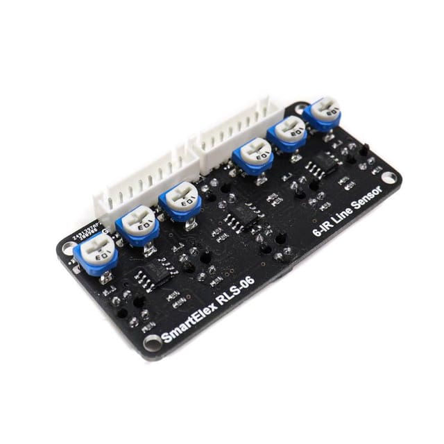
This SmartElex RLS-06 Analog & Digital Line Sensor Array has 6 IR LED/phototransistor pairs, making it a great detector for a line-following robot. Each sensor has its own digital and analog output. potentiometer to adjust the sensitivity of the individual sensors.
The TCRT5000 reflectance sensors array is intended as a line sensor, but it can be used as a general-purpose proximity or reflectance sensor. The module is a convenient carrier for eight IR emitter and receiver (phototransistor) pairs evenly spaced at intervals.
Each phototransistor is connected to a pull-up resistor to form a voltage divider that produces an analog voltage output between 0V and VIN (which is typically 5V) as a function of the reflected IR. The lower output voltage is an indication of greater reflection.
The outputs are all independent, but the LEDs are arranged in pairs to halve current consumption. The LEDs are controlled by a MOSFET with a gate normally pulled high, allowing the LEDs to be turned off by setting the MOSFET gate to a low voltage. Turning the LEDs off might be advantageous for limiting power consumption when the sensors are not in use or for varying the effective brightness of the LEDs through PWM control.
The LED current-limiting resistors for 5V operation are arranged in two stages; this allows a simple bypass of one stage to enable operation at 3.3V. The LED current is approximately 20-25mA, making the total board consumption just under 100?mA. The schematic diagram of the module is shown above.
Features :
- Potentiometer to adjust the sensitivity of the individual sensors.
- The module is a convenient carrier for six IR emitter and receiver pairs evenly paced.
- Uses 6 sensors for best resolution
- Great useful in building fast line following and grid navigating robots
- Comes with easy to use digital outputs that can be connected directly to microcontrollers
- The array has mounting holes of 3mm diameter for easy mounting
Package Includes:
1 xSmartElex RLS-06 Analog & Digital Line Sensor Array
- Home
- MARKETPLACE
- SmartElex RLS-06 Analog & Digital Line Sensor Array
SmartElex RLS-06 Analog & Digital Line Sensor Array
SIZE GUIDE
- Shipping in 10-12 Working Days
Description of product
Click here to see why SmartElex is different!
This SmartElex RLS-06 Analog & Digital Line Sensor Array has 6 IR LED/phototransistor pairs, making it a great detector for a line-following robot. Each sensor has its own digital and analog output. potentiometer to adjust the sensitivity of the individual sensors.
The TCRT5000 reflectance sensors array is intended as a line sensor, but it can be used as a general-purpose proximity or reflectance sensor. The module is a convenient carrier for eight IR emitter and receiver (phototransistor) pairs evenly spaced at intervals.
Each phototransistor is connected to a pull-up resistor to form a voltage divider that produces an analog voltage output between 0V and VIN (which is typically 5V) as a function of the reflected IR. The lower output voltage is an indication of greater reflection.
The outputs are all independent, but the LEDs are arranged in pairs to halve current consumption. The LEDs are controlled by a MOSFET with a gate normally pulled high, allowing the LEDs to be turned off by setting the MOSFET gate to a low voltage. Turning the LEDs off might be advantageous for limiting power consumption when the sensors are not in use or for varying the effective brightness of the LEDs through PWM control.
The LED current-limiting resistors for 5V operation are arranged in two stages; this allows a simple bypass of one stage to enable operation at 3.3V. The LED current is approximately 20-25mA, making the total board consumption just under 100?mA. The schematic diagram of the module is shown above.
Features :
- Potentiometer to adjust the sensitivity of the individual sensors.
- The module is a convenient carrier for six IR emitter and receiver pairs evenly paced.
- Uses 6 sensors for best resolution
- Great useful in building fast line following and grid navigating robots
- Comes with easy to use digital outputs that can be connected directly to microcontrollers
- The array has mounting holes of 3mm diameter for easy mounting
Package Includes:
1 xSmartElex RLS-06 Analog & Digital Line Sensor Array
Related products
NEWSLETTER
Subscribe to get Email Updates!
Thanks for subscribe.
Your response has been recorded.
INFORMATION
ACCOUNT
ADDRESS
Tenet Technetronics# 2514/U, 7th 'A' Main Road, Opp. to BBMP Swimming Pool, Hampinagar, Vijayanagar 2nd Stage.
Bangalore
Karnataka - 560104
IN
Tenet Technetronics focuses on “Simplifying Technology for Life” and has been striving to deliver the same from the day of its inception since 2007. Founded by young set of graduates with guidance from ardent professionals and academicians the company focuses on delivering high quality products to its customers at the right cost considering the support and lifelong engagement with customers. “We don’t believe in a sell and forget model “and concentrate and building relationships with customers that accelerates, enhances as well as provides excellence in their next exciting project.


