
-
TRANSDUCERS
- TRANSDUCERS
-
BASIC COMPONENTS DK
- BASIC COMPONENTS DK
-
MARKETPLACE
- MARKETPLACE
-
DEVELOPMENT BOARDS & KITS
- DEVELOPMENT BOARDS & KITS
-
CABLE ASSEMBLIES
- CABLE ASSEMBLIES
-
RF AND WIRELESS
- RF AND WIRELESS
-
BOXES ENCLOSURES RACKS
- BOXES ENCLOSURES RACKS
-
AUDIO PRODUCTS
- AUDIO PRODUCTS
-
ARTILA
- ARTILA
-
FANS-BLOWERS-THERMAL MANAGEMENT
- FANS-BLOWERS-THERMAL MANAGEMENT
-
WIRELESS MODULES
- WIRELESS MODULES
-
TERMINALS
- TERMINALS
-
Cables/Wires
- Cables/Wires
-
SINGLE BOARD COMPUTER
- SINGLE BOARD COMPUTER
-
BREAKOUT BOARDS
- BREAKOUT BOARDS
-
LED
- LED
-
TEST AND MEASUREMENT
- TEST AND MEASUREMENT
-
POTENTIONMETERS AND VARIABLE RESISTORS
- POTENTIONMETERS AND VARIABLE RESISTORS
-
DEVELOPMENT BOARDS AND IC's
- DEVELOPMENT BOARDS AND IC's
-
EMBEDDED COMPUTERS
- EMBEDDED COMPUTERS
-
OPTOELECTRONICS
- OPTOELECTRONICS
-
INDUSTRAL AUTOMATION AND CONTROL
- INDUSTRAL AUTOMATION AND CONTROL
-
COMPUTER EQUIPMENT
- COMPUTER EQUIPMENT
-
CONNECTORS & INTERCONNECTS
- CONNECTORS & INTERCONNECTS
-
MAKER/DIY EDUCATIONAL
- MAKER/DIY EDUCATIONAL
-
TOOLS
- TOOLS
-
MOTORS/ACTUATORS/SOLEENOIDS/DRIVERS
- MOTORS/ACTUATORS/SOLEENOIDS/DRIVERS
-
FPGA HARDWARE
- FPGA HARDWARE
-
POWER SUPPLIES
- POWER SUPPLIES
-
ROBOTICS & AUTOMATION
- ROBOTICS & AUTOMATION

Description
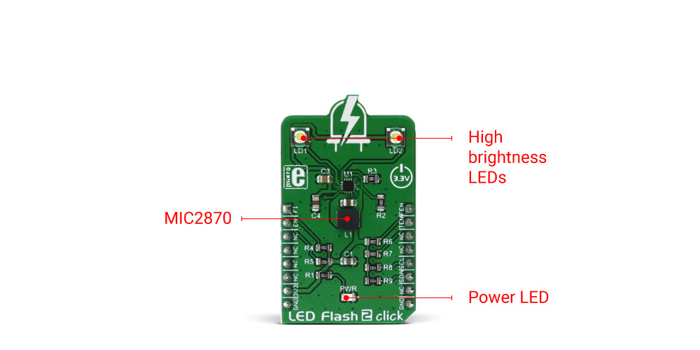
LED Flash 2 click is a powerful flash/torch click, featuring the MIC2870 from Microchip, a high-efficiency flash LED driver, optimized for driving one or two high-brightness camera flash LEDs. The MIC2870 IC can drive one high brightness LED up to 1.5A or two high brightness LEDs, up to 750mA each. Two high brightness LEDs are already mounted on the Led Flash 2 click, so the click board is ready to be used right away.
LED Flash 2 click provides two modes of operation - the Torch mode and the Flash mode. While working in Torch mode, the output current is adjusted so that the continuous operation of the LEDs is provided. When it is set to work in the Flash mode, the LED current is maximized and while giving a powerful light, it can not work for prolonged periods. The Torch mode will turn the click board™ into a simple handheld torchlight, while the Flash mode is good for using the LEDs as the camera flash, providing good images in various low light situations.
How does it work?
The main active part of this click board™ is the MIC2870, a synchronous boost flash LED driver, which can be set to work in a Flash or Torch mode. It uses integrated inductive boost converter with 2 MHz switching frequency, which allows the use of a very small inductor and output capacitor. The operating mode can be set both with the dedicated pins and the I2C interface commands. The I2C interface is quite fast and it can operate up to 3.4 MHz. The I2C clock speed ensures fast communication and therefore minimal response time. This is a very important feature when used as a flashlight for the camera applications, where an instant reaction is needed.
The click board comes equipped with the two XPCWHT-L1-R250, high brighness LED elements by Cree, Inc.
When working in the Flash mode, the current through the single LED channel is maximized and determined by the resistors, connected to the FRSET input of the MIC2870 IC. On the Led Flash 2 click, the maximum current is set by the 10K resistor, to 750mA per LED channel. This current can be additionally limited by selecting the desired flash current level percentage in the flash control register (01h).
The flash safety timeout feature automatically shuts down the flash current, if the flash mode is enabled for an extended period of time. The timeout can be set by the corresponding bits in the flash control register (01h). For more information about the available registers and their values, consult the MIC2870 datasheet.
Flash inhibition pin, or the FI pin - routed to the mikroBUS™ AN pin, with the corresponding bit in the Torch control register (02h), is used to limit the Flash mode current value to the Torch mode current value. This will effectively override the Flash mode.
For the Torch mode operation, the current is set to a lower value than for the Flash mode - with the 10K resistor connected to the TRSET, this current is set to 187.5mA. Similar as for the Flash mode, the torch control register (02h) controls the percentage of the current, set by the TRSET resistor.
Rising edge on the TEN or FEN - routed to the mikroBUS™ INT and PWM pins, will activate the Torch mode or the Flash mode, respectively. These modes can also be activated by setting the corresponding bits in the control registers.
EN pin - routed to the mikroBUS™ RST pin, along with the corresponding bit in the status register (00h), is used to enable the MIC2870 IC. Setting this pin to a HIGH logic level will put the IC into the standby state. Driving this pin low for more than 1 second - or setting the bit to a low state will put the MIC2870 IC into a shutdown mode, the lowest power consumption mode for this click board™.
All the control pins are internally pulled to a LOW logic state, so there is no need to use any pull-down resistors for this purpose, which further simplifies application designs with this click board™.
Specifications
| Type | LED Segment |
| Applications | Flash or torch light for various hand-held devices, such as the small camera light or a cell phone flashlight. It can be also used as a signal light, bicycle light, car taillight, etc. |
| On-board modules | MIC2870 - synchronous boost flash LED driver from Microchip |
| Key Features | High efficiency LED driver operating in two modes - Flash and Torch. Drives two high brightness LEDs with up to 750mA, short circuit and open circuit detection on the output, easy to use via the dedicated pins or ultra fast I2C interface, up to 3.4MHz. |
| Interface | GPIO,I2C |
| Input Voltage | 3.3V |
| Click board size | M (42.9 x 25.4 mm) |
- Home
- LED Flash 2 click

LED Flash 2 click
SIZE GUIDE
- Shipping in 10-12 Working days
- http://cdn.storehippo.com/s/59c9e4669bd3e7c70c5f5e6c/ms.products/5aa6205517bba4f297981562/images/5aa6205517bba4f297981563/5aa6204bef5c12f2969bb07b/5aa6204bef5c12f2969bb07b.jpg
Description of product
Description
LED Flash 2 click is a powerful flash/torch click, featuring the MIC2870 from Microchip, a high-efficiency flash LED driver, optimized for driving one or two high-brightness camera flash LEDs. The MIC2870 IC can drive one high brightness LED up to 1.5A or two high brightness LEDs, up to 750mA each. Two high brightness LEDs are already mounted on the Led Flash 2 click, so the click board is ready to be used right away.
LED Flash 2 click provides two modes of operation - the Torch mode and the Flash mode. While working in Torch mode, the output current is adjusted so that the continuous operation of the LEDs is provided. When it is set to work in the Flash mode, the LED current is maximized and while giving a powerful light, it can not work for prolonged periods. The Torch mode will turn the click board™ into a simple handheld torchlight, while the Flash mode is good for using the LEDs as the camera flash, providing good images in various low light situations.
How does it work?
The main active part of this click board™ is the MIC2870, a synchronous boost flash LED driver, which can be set to work in a Flash or Torch mode. It uses integrated inductive boost converter with 2 MHz switching frequency, which allows the use of a very small inductor and output capacitor. The operating mode can be set both with the dedicated pins and the I2C interface commands. The I2C interface is quite fast and it can operate up to 3.4 MHz. The I2C clock speed ensures fast communication and therefore minimal response time. This is a very important feature when used as a flashlight for the camera applications, where an instant reaction is needed.
The click board comes equipped with the two XPCWHT-L1-R250, high brighness LED elements by Cree, Inc.
When working in the Flash mode, the current through the single LED channel is maximized and determined by the resistors, connected to the FRSET input of the MIC2870 IC. On the Led Flash 2 click, the maximum current is set by the 10K resistor, to 750mA per LED channel. This current can be additionally limited by selecting the desired flash current level percentage in the flash control register (01h).
The flash safety timeout feature automatically shuts down the flash current, if the flash mode is enabled for an extended period of time. The timeout can be set by the corresponding bits in the flash control register (01h). For more information about the available registers and their values, consult the MIC2870 datasheet.
Flash inhibition pin, or the FI pin - routed to the mikroBUS™ AN pin, with the corresponding bit in the Torch control register (02h), is used to limit the Flash mode current value to the Torch mode current value. This will effectively override the Flash mode.
For the Torch mode operation, the current is set to a lower value than for the Flash mode - with the 10K resistor connected to the TRSET, this current is set to 187.5mA. Similar as for the Flash mode, the torch control register (02h) controls the percentage of the current, set by the TRSET resistor.
Rising edge on the TEN or FEN - routed to the mikroBUS™ INT and PWM pins, will activate the Torch mode or the Flash mode, respectively. These modes can also be activated by setting the corresponding bits in the control registers.
EN pin - routed to the mikroBUS™ RST pin, along with the corresponding bit in the status register (00h), is used to enable the MIC2870 IC. Setting this pin to a HIGH logic level will put the IC into the standby state. Driving this pin low for more than 1 second - or setting the bit to a low state will put the MIC2870 IC into a shutdown mode, the lowest power consumption mode for this click board™.
All the control pins are internally pulled to a LOW logic state, so there is no need to use any pull-down resistors for this purpose, which further simplifies application designs with this click board™.
Specifications
| Type | LED Segment |
| Applications | Flash or torch light for various hand-held devices, such as the small camera light or a cell phone flashlight. It can be also used as a signal light, bicycle light, car taillight, etc. |
| On-board modules | MIC2870 - synchronous boost flash LED driver from Microchip |
| Key Features | High efficiency LED driver operating in two modes - Flash and Torch. Drives two high brightness LEDs with up to 750mA, short circuit and open circuit detection on the output, easy to use via the dedicated pins or ultra fast I2C interface, up to 3.4MHz. |
| Interface | GPIO,I2C |
| Input Voltage | 3.3V |
| Click board size | M (42.9 x 25.4 mm) |
NEWSLETTER
Subscribe to get Email Updates!
Thanks for subscribe.
Your response has been recorded.
INFORMATION
ACCOUNT
ADDRESS
Tenet Technetronics# 2514/U, 7th 'A' Main Road, Opp. to BBMP Swimming Pool, Hampinagar, Vijayanagar 2nd Stage.
Bangalore
Karnataka - 560104
IN
Tenet Technetronics focuses on “Simplifying Technology for Life” and has been striving to deliver the same from the day of its inception since 2007. Founded by young set of graduates with guidance from ardent professionals and academicians the company focuses on delivering high quality products to its customers at the right cost considering the support and lifelong engagement with customers. “We don’t believe in a sell and forget model “and concentrate and building relationships with customers that accelerates, enhances as well as provides excellence in their next exciting project.